Scanning system
Introduction
This configuration may be useful for building a galvanometer controller for an optical scanner or a scanning coil controller for a scanning electron microscope.
Interesting links
Some interesting links on scanning and imaging techniques:
Scanning and Image Reconstruction Techniques in Confocal Laser Scanning Microscopy
Spectral Imaging: Active hyperspectral sensing and imaging for remote spectroscopy applications
Hardware
The system outputs the line scan signal to OUT1 and the raster scan signal to OUT2. The trigger and S&H pulses are available from the pins DIO0_N and DIO1_N on the E1 connector. The analog signals corresponding to each pixel are input to IN1 and IN2.
The basic blocks of the system are shown in the following diagram:
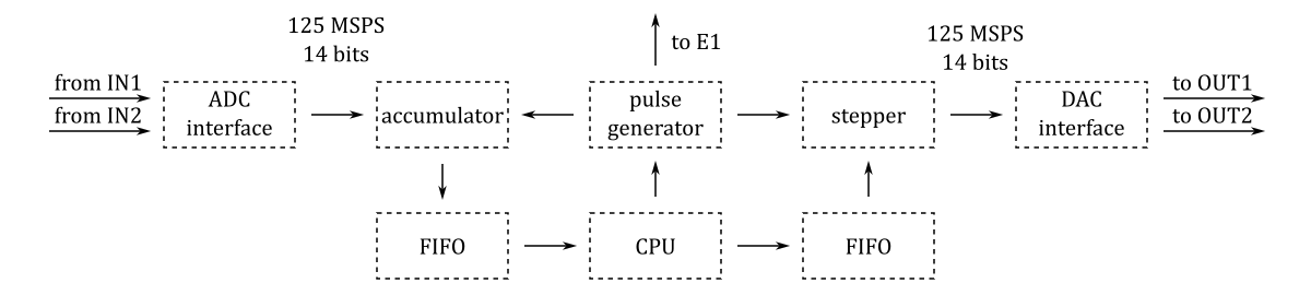
The projects/scanner directory contains one Tcl file block_design.tcl that instantiates, configures and interconnects all the needed IP cores.
Software
The projects/scanner/server directory contains the source code of the TCP server (scanner.c) that receives control commands and transmits the data to the control program running on a remote PC.
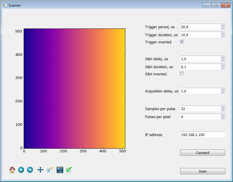
The projects/scanner/client directory contains the source code of the control program (scanner.py).
Getting started with GNU/Linux
- Download customized SD card image zip file.
- Copy the contents of the SD card image zip file to a micro SD card.
- Install the micro SD card in the Red Pitaya board and connect the power.
- Install required Python libraries:
sudo apt-get install python3-numpy python3-matplotlib python3-pyqt5- Clone the source code repository:
git clone https://github.com/pavel-demin/red-pitaya-notes- Run the control program:
cd red-pitaya-notes/projects/scanner/client
python3 scanner.py- Type in the IP address of the Red Pitaya board and press Connect button.
- Adjust trigger and S&H pulses and number of samples per pixel.
- Press Scan button.
Building from source
The installation of the development machine is described at this link.
The structure of the source code and of the development chain is described at this link.
Setting up the Vitis and Vivado environment:
source /opt/Xilinx/2025.1/Vitis/settings64.shCloning the source code repository:
git clone https://github.com/pavel-demin/red-pitaya-notes
cd red-pitaya-notes
Building scanner.bit:
make NAME=scanner bitBuilding SD card image zip file:
source helpers/build-project.sh scanner