Multiband FT8 transceiver
Short description
This project implements a standalone multiband FT8 transceiver with all the FT8 signal processing done by STEMlab SDR in the following way:
- simultaneously record FT8 signals from sixteen bands
- use FPGA for all the conversions needed to produce .c2 files (complex 32-bit floating-point data at 4000 samples per second)
- use on-board CPU to process the .c2 files with the FT8 decoder
With this configuration, it is enough to connect STEMlab SDR to an antenna and to a network. After switching STEMlab SDR on, it will automatically start operating as a FT8 receiver.
Hardware
The FPGA configuration consists of sixteen identical digital down-converters (DDC). Their structure is shown in the following diagram:
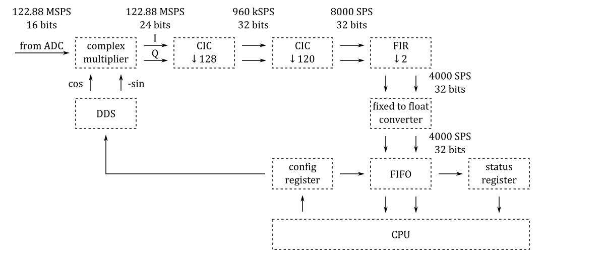
The DDC output contains complex 32-bit floating-point data at 4000 samples per second.
The projects/sdr_transceiver_ft8_122_88 directory contains three Tcl files: block_design.tcl, rx.tcl and tx.tcl. The code in these files instantiates, configures and interconnects all the needed IP cores.
Software
The write-c2-files.c program accumulates 236000 samples at 4000 samples per second for each of the sixteen bands and saves the samples to sixteen .c2 files.
The recorded .c2 files are processed with the FT8 decoder.
The decode-ft8.sh script launches write-c2-files and ft8d one after another. This script is run every minute by the following cron entry in ft8.cron:
* * * * * cd /dev/shm && /media/mmcblk0p1/apps/sdr_transceiver_ft8_122_88/decode-ft8.sh >> decode-ft8.log 2>&1 &GPS interface
A GPS module can be used for the time synchronization and for the automatic measurement and correction of the frequency deviation.
The PPS signal should be connected to the pin DIO3_N of the extension connector E1. The UART interface should be connected to the UART pins of the extension connector E2.
The measurement and correction of the frequency deviation is disabled by default and should be enabled by uncommenting the following line in ft8.cron:
* * * * * cd /dev/shm && /media/mmcblk0p1/apps/common_tools/update-corr.sh 122.88 >> update-corr.log 2>&1 &Getting started
- Download SD card image zip file (more details about the SD card image can be found at this link).
- Copy the contents of the SD card image zip file to a micro SD card.
- Optionally, to start the application automatically at boot time, copy its
start.shfile fromapps/sdr_transceiver_ft8_122_88to the topmost directory on the SD card. - Install the micro SD card in the STEMlab SDR board and connect the power.
Configuring FT8 receiver
All the configuration files and scripts can be found in the apps/sdr_transceiver_ft8_122_88 directory on the SD card.
To enable uploads, the CALL and GRID variables should be specified in upload-ft8.sh. These variables should be set to the call sign of the receiving station and its 6-character Maidenhead grid locator.
The frequency correction ppm value can be adjusted by editing the corr parameter in write-c2-files.cfg.
The bands list in write-c2-files.cfg contains all the FT8 frequencies. They can be enabled or disabled by uncommenting or by commenting the corresponding lines.
Building from source
The installation of the development machine is described at this link.
The structure of the source code and of the development chain is described at this link.
Setting up the Vitis and Vivado environment:
source /opt/Xilinx/2025.2/Vitis/settings64.shCloning the source code repository:
git clone https://github.com/pavel-demin/red-pitaya-notes
cd red-pitaya-notes
Building sdr_transceiver_ft8_122_88.bit:
make NAME=sdr_transceiver_ft8_122_88 PART=xc7z020clg400-1 bitBuilding SD card image zip file:
source helpers/build-all.sh