SDR transceiver compatible with HPSDR
Introduction
The High Performance Software Defined Radio (HPSDR) project is an open source hardware and software project that develops a modular Software Defined Radio (SDR) for use by radio amateurs and short wave listeners.
This version of the Red Pitaya SDR transceiver makes it usable with the software developed by the HPSDR project and other SDR programs that support the HPSDR/Metis communication protocol.
This SDR transceiver emulates a HPSDR transceiver similar to Hermes with a network interface, two receivers and one transmitter.
The HPSDR/Metis communication protocol is described in the following documents:
Hardware
The implementation of this SDR transceiver is similar to the previous version of the SDR transceiver that is described in more details at this link.
The main problem in emulating the HPSDR hardware with Red Pitaya is that the Red Pitaya ADC sample rate is 125 MSPS and the HPSDR ADC sample rate is 122.88 MSPS.
To address this problem, this version contains a set of FIR filters for fractional sample rate conversion.
The resulting I/Q data rate is configurable and four settings are available: 48, 96, 192, 384 kSPS.
The tunable frequency range covers from 0 Hz to 61.44 MHz.
This SDR transceiver consists of five digital down-converters (DDC) and one digital up-converter (DUC). The first three digital down-converters are connected to the ADC channels. Two additional digital down-converters are required for the amplifier linearization system. One of them is connected to one of the ADC channels and the other is connected to the output of the digital up-converter.
The basic blocks of the digital down-converters are shown in the following diagram:
![]()
The digital up-converter consists of similar blocks but arranged in an opposite order:
![]()
The projects/sdr_transceiver_hpsdr directory contains three Tcl files: block_design.tcl, rx.tcl, tx.tcl. The code in these files instantiates, configures and interconnects all the needed IP cores.
The projects/sdr_transceiver_hpsdr/filters directory contains the source code of the R scripts used to calculate the coefficients of the FIR filters.
The projects/sdr_transceiver_hpsdr/server directory contains the source code of the UDP server (sdr-transceiver-hpsdr.c) that receives control commands and transmits/receives the I/Q data streams to/from the SDR programs.
RF, GPIO and XADC connections
- input for RX1 is connected to IN1
- inputs for RX2 and RX3 are connected to IN2
- output for TX is connected to OUT1
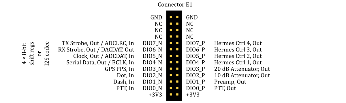
- output for a RX/TX switch control (PTT-out) is connected to pin DIO0_P of the extension connector E1
- output for a pre-amplifier/attenuator control is connected to pin DIO1_P of the extension connector E1 (this pin is controlled by the first ATT combo-box in PowerSDR mRX PS)
- outputs for 10 dB and 20 dB attenuators control are connected to the pins DIO2_P - DIO3_P of the extension connector E1
- outputs for Hermes Ctrl pins are connected to the pins DIO4_P - DIO7_P of the extension connector E1
- inputs for PTT, DASH and DOT are connected to the pins DIO0_N, DIO1_N and DIO2_N of the extension connector E1
- slow analog inputs can be used for the forward (Analog input 0) and reverse (Analog input 1) power measurement
I2S connections
The I2S interface is sharing pins with the ALEX interface. So, the two can't be used simultaneously. The supported I2S audio codecs are TLV320AIC23B and WM8731. The I2S audio codecs should be clocked with a 12.288 MHz oscillator crystal.
The I2S interface should be connected to the extension connector E1 as shown in the above diagram. The I2C interface should be connected to the I2C pins of the extension connector E2.
ALEX connections
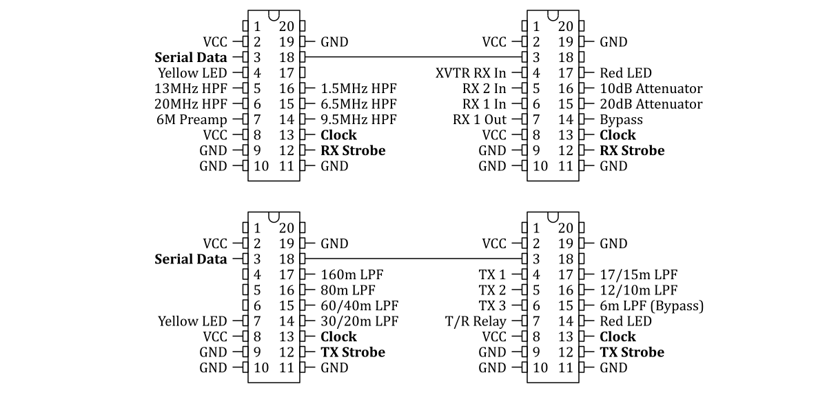
The ALEX module can be connected to the pins DIO4_N (Serial Data), DIO5_N (Clock), DIO6_N (RX Strobe) and DIO7_N (TX Strobe) of the extension connector E1. The board and the protocol are described in the ALEX manual.
The HPSDR signals sent to the TPIC6B595 chips are shown in the following diagram:
I2C connections
This interface is designed by Peter DC2PD. The sdr-transceiver-hpsdr.c server communicates with one or two PCA9555 chips connected to the I2C pins of the extension connector E2.
HPSDR signals sent to the PCA9555 chip at address 0 (0x20):
| PCA9555 pins | HPSDR signals |
|---|---|
| P00 - P06 | Open Collector Outputs on Penelope or Hermes |
| P07 - P10 | Attenuator (00 = 0dB, 01 = 10dB, 10 = 20dB, 11 = 30dB) |
| P11 - P12 | Rx Antenna (00 = none, 01 = Rx1, 10 = Rx2, 11 = XV) |
| P13 - P14 | Tx Relay (00 = Tx1, 01= Tx2, 10 = Tx3) |
HPSDR signals sent to the PCA9555 chip at address 1 (0x21):
| PCA9555 pins | HPSDR signals |
|---|---|
| P00 | select 13MHz HPF (0 = disable, 1 = enable) |
| P01 | select 20MHz HPF (0 = disable, 1 = enable) |
| P02 | select 9.5MHz HPF (0 = disable, 1 = enable) |
| P03 | select 6.5MHz HPF (0 = disable, 1 = enable) |
| P04 | select 1.5MHz HPF (0 = disable, 1 = enable) |
| P05 | bypass all HPFs (0 = disable, 1 = enable) |
| P06 | 6M low noise amplifier (0 = disable, 1 = enable) |
| P07 | disable T/R relay (0 = enable, 1 = disable) |
| P10 | select 30/20m LPF (0 = disable, 1 = enable) |
| P11 | select 60/40m LPF (0 = disable, 1 = enable) |
| P12 | select 80m LPF (0 = disable, 1 = enable) |
| P13 | select 160m LPF (0 = disable, 1 = enable) |
| P14 | select 6m LPF (0 = disable, 1 = enable) |
| P15 | select 12/10m LPF (0 = disable, 1 = enable) |
| P16 | select 17/15m LPF (0 = disable, 1 = enable) |
Signals sent to the PCA9555 chip at address 3 (0x23):
| PCA9555 pins | signals |
|---|---|
| P00 - P03 | BCD code for Rx1 band |
| P04 - P07 | BCD code for Rx2 band |
| P10 | Tx frequency (0 if Tx freq. = Rx1 freq., 1 if Tx freq. = Rx2 freq.) |
| P11 - P12 | ATT1 |
| P13 - P14 | ATT2 |
| P15 | disable T/R relay (0 = enable, 1 = disable) |
| P16 | bypass all HPFs (0 = disable, 1 = enable) |
More information about the I2C interface can be found at this link.
Software
This SDR transceiver should work with most of the programs that support the HPSDR/Metis communication protocol:
PowerSDR mRX PS that can be downloaded from this link
QUISK with the
hermes/quisk_conf.pyconfiguration fileghpsdr3-alex client-server distributed system
openHPSDR Android Application that is described in more details at this link
Java desktop application based on openHPSDR Android Application
Getting started
- Download SD card image zip file (more details about the SD card image can be found at this link).
- Copy the contents of the SD card image zip file to a micro SD card.
- Optionally, to start the application automatically at boot time, copy its
start.shfile fromapps/sdr_transceiver_hpsdrto the topmost directory on the SD card. - Install the micro SD card in the Red Pitaya board and connect the power.
- Install and run one of the HPSDR programs.
Configuring inputs and outputs
The sdr-transceiver-hpsdr program running on the Red Pitaya board expects six command line arguments:
sdr-transceiver-hpsdr 1 2 2 2 1 2The first four arguments are for the receivers (RX1, RX2, RX3, RX4), where 1 corresponds to IN1 and 2 corresponds to IN2.
The last two arguments are for the outputs (OUT1, OUT2), where 1 corresponds to the TX signal and 2 corresponds to the envelope signal.
For example, to send the TX signal to OUT2, the corresponding line in start.sh should be edited and the last argument should be set to 1:
sdr-transceiver-hpsdr 1 2 2 2 1 1Amplifier linearization
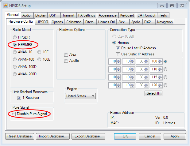
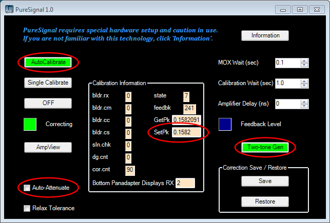
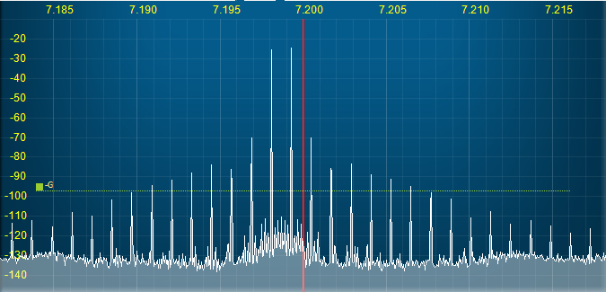
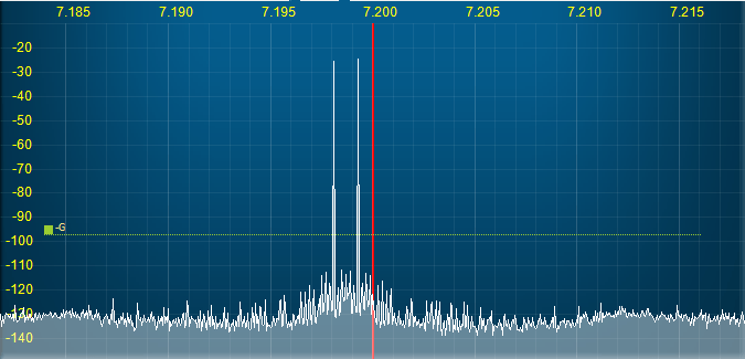
PowerSDR mRX PS includes an amplifier linearization system called [PureSignal](https://github.com/TAPR/OpenHPSDR-PowerSDR/raw/master/Documentation/Pure Signal/PureSignal.pdf). The following screenshots show what settings should be adjusted when using it with Red Pitaya. To access the "Calibration Information" panel press Ctrl+Alt+i. The attenuated feedback signal from the amplifier should be connected to IN2.
The following spectra illustrate how the amplifier linearization works with the Red Pitaya output (OUT1) connected to the Red Pitaya input (IN2) with a 50 Ohm termination.
CW functionality
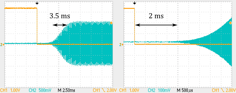
The CW keyer can be used with a straight or iambic key connected to the pins DIO1_N and DIO2_N of the extension connector E1. The CW signal is generated when one of the CW modes is selected in PowerSDR mRX PS and the pins DIO1_N and DIO2_N are connected to GND.
The ramp generator is programmable. The default ramp's shape is the step response of the 4-term Blackman-Harris window. It's inspired by the "CW Shaping in DSP Software" article appeared in the May/June, 2006 issue of QEX.
The measured delay between the key press and the start of the RF signal is about 2 ms. The 10%-90% rise time of the signal is about 3.5 ms.
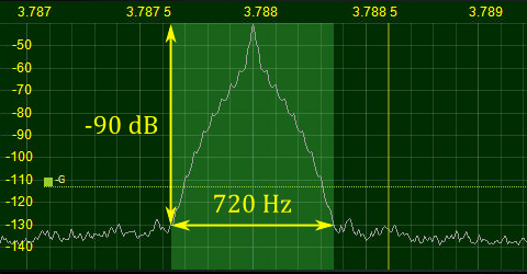
The following figure shows the spectrum of the CW signal keyed at 50 WPM.
Building from source
The installation of the development machine is described at this link.
The structure of the source code and of the development chain is described at this link.
Setting up the Vitis and Vivado environment:
source /opt/Xilinx/2025.1/Vitis/settings64.shCloning the source code repository:
git clone https://github.com/pavel-demin/red-pitaya-notes
cd red-pitaya-notes
Building sdr_transceiver_hpsdr.bit:
make NAME=sdr_transceiver_hpsdr bitBuilding SD card image zip file:
source helpers/build-all.sh